


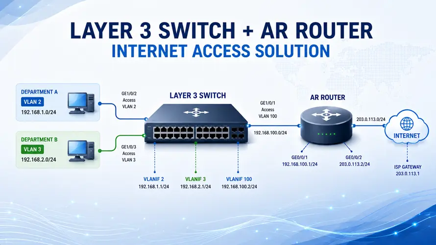
In enterprise campus networks, a common design is to use a Huawei Layer 3 campus switch as S5730 series, while an upstream router provides Internet access. This article provides a complete configuration example, including CLI commands, to help engineers quickly deploy this solution.
Network Overview
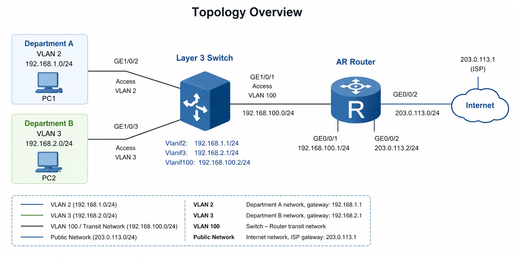
- VLAN 2 → 192.168.1.0/24
- VLAN 3 → 192.168.2.0/24
- Switch–Router link → 192.168.100.0/24
- Public network → 203.0.113.0/24
The Layer 3 switch acts as:
- Gateway for users
- DHCP server
The router handles:
- Internet routing
- NAT translation
Configuration Steps
1. Configure the Layer 3 Switch
1.1 Create VLANs and Assign Access Ports
[HUAWEI] sysname Switch[Switch] vlan batch 2 3 100[Switch] interface GE 1/0/2
[Switch-GE1/0/2] port link-type access
[Switch-GE1/0/2] port default vlan 2
[Switch-GE1/0/2] quit[Switch] interface GE 1/0/3
[Switch-GE1/0/3] port link-type access
[Switch-GE1/0/3] port default vlan 3
[Switch-GE1/0/3] quit
1.2 Configure VLANIF Interfaces (User Gateways)
[Switch-Vlanif2] ip address 192.168.1.1 255.255.255.0
[Switch-Vlanif2] quit[Switch] interface Vlanif 3
[Switch-Vlanif3] ip address 192.168.2.1 255.255.255.0
[Switch-Vlanif3] quit
1.3 Configure Uplink to Router
[Switch-GE1/0/1] port link-type access
[Switch-GE1/0/1] port default vlan 100
[Switch-GE1/0/1] quit[Switch] interface Vlanif 100
[Switch-Vlanif100] ip address 192.168.100.2 255.255.255.0
[Switch-Vlanif100] quit
1.4 Configure Default Route
1.5 Enable DHCP Server
[Switch] dhcp enable
[Switch] interface Vlanif 2
[Switch-Vlanif2] dhcp select interface
[Switch-Vlanif2] dhcp server dns-list 114.114.114.114 223.5.5.5
[Switch-Vlanif2] quit
[Switch] interface Vlanif 3
[Switch-Vlanif3] dhcp select interface
[Switch-Vlanif3] dhcp server dns-list 114.114.114.114 223.5.5.5
[Switch-Vlanif3] quit
2. Configure the Router
2.1 Configure Interfaces
[HUAWEI] sysname Router[Router] interface GigabitEthernet 0/0/1
[Router-GE0/0/1] ip address 192.168.100.1 255.255.255.0
[Router-GE0/0/1] quit[Router] interface GigabitEthernet 0/0/2
[Router-GE0/0/2] ip address 203.0.113.2 255.255.255.0
[Router-GE0/0/2] quit
2.2 Configure Routing
[Router] ip route-static 192.168.0.0 255.255.0.0 192.168.100.2
2.3 Configure NAT
[Router-acl-basic-2001] rule 5 permit source 192.168.0.0 0.0.255.255
[Router-acl-basic-2001] quit[Router] interface GigabitEthernet 0/0/2
[Router-GE0/0/2] nat outbound 2001
[Router-GE0/0/2] quit
3. Verification
Configure PCs:
- PC1 → 192.168.1.2 / Gateway 192.168.1.1
- PC2 → 192.168.2.2 / Gateway 192.168.2.1
Test:
If successful:
- Inter-VLAN routing works
- DHCP works
- Internet access is available
Final Thoughts
This configuration demonstrates a typical enterprise deployment where:
- The Layer 3 switch handles internal routing and user access
- The router provides external connectivity and NAT
It is a scalable, efficient, and widely used architecture in campus and SME networks.